

Progressively Develop Conceptual, Logical and Physical ERDs
 Entity-Relationship Diagrams (ERDs) come in 3 types in general. They describe data models on 3 levels of abstraction – conceptual, logical and physical, ranging from high-level ideas to details required for implementation. With Visual Paradigm, you can systematically and easily progress through these stages of development in data modeling.
Far from a copy & paste function only, you can actually develop a logical or physical design from a conceptual diagram, with the design tracing ability.
For example, if a new staff comes on board to work on a project’s physical design ERD, he/she can click on a database table to trace where this idea originally comes from in the conceptual diagram (to which it is inherently linked by Visual Paradigm). This function will not only bring relief to the staff but also help safeguard the project’s quality along the way.
In this article, we will show you an example on how to create a conceptual ERD and transit it to a physical ERD, from which you can generate a DLL file for database implementation.
Note : For simplicity reason, we will demonstrate how to go from conceptual design to physical design only, skipping the logical design. Visual Paradigm Standard Edition will be used in the demonstration.
Create Conceptual ERD
To create the conceptual ERD
- In Visual Paradigm, select View > Project Browser.
Open Project Browser
- Press the New Model.
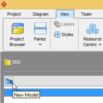
Create New Model
- Name the model as Conceptual Model in the Model Specification, and press OK to proceed.
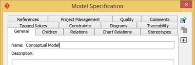
Name it as Conceptual Model
- The Conceptual Model is now being created. Select the Conceptual Model and press Add New Diagram.
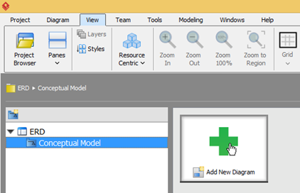
Create new diagram under Conceptual Model
- In the New Diagram dialog, click on the search field and enter erd to locate the Entity Relationship Diagram.
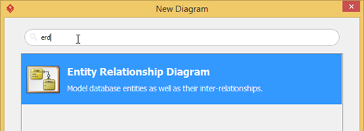
Create new ERD
- Name the diagram as Sales Order Conceptual Design, and press OK to create the diagram.
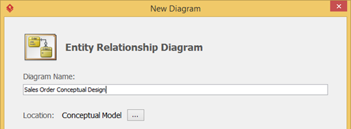
Name the ERD as Sales Order Conceptual Design
- Once the diagram is created, the top right hand corner will indicate which type of ERD it is. As we create ERD under Conceptual Model, by default it will automatically set to Conceptual Model.
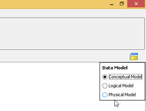
Make sure the ERD is created in Conceptual type
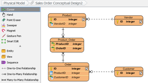
- Now let’s create our conceptual ERD.
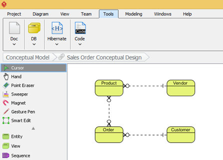
Create Conceptual ERD
Generate Physical ERD from Conceptual ERD
Once we created the conceptual ERD, we can then generate physical ERD from it. To generate the physical ERD:
- Right click on the blank area on the conceptual ERD, and select Utilities > Transit to Physical ERD…
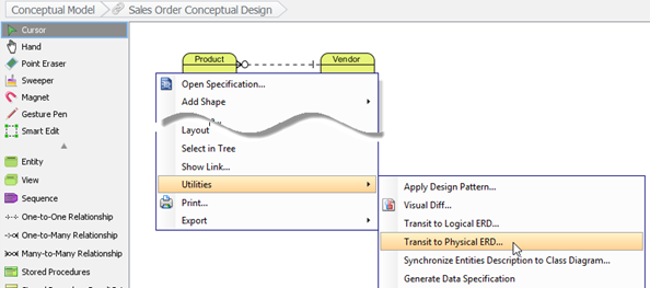
Transit Conceptual ERD to Physical ERD
- Select the project root node in the Select Parent Model of New Physical ERD dialog, and press the New Model button on the top right hand corner.
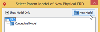
Select project root for create new model
- Name the newly created model as Physical Model. Press OK to proceed.
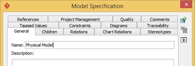
Name the new model as Physical Model
- Select the Physical Model and press OK.
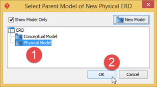
Select Physical Model for generate physical ERD
- After that the physical ERD is being generated. You will see that the primary key and foreign keys are automatically generated in the ER model, also the many-to-many relationship (between Product and Order) is automatically resolved into two one-to-many relationships (for implementation).
Physical ERD being generated
- By default the name of the newly generated ERD will be similar to the original one. Let’s rename it to reflect the reality. Double click the diagram name in the breadcrumb and rename it Sales Order Physical Design. Press Enter to confirm the change.
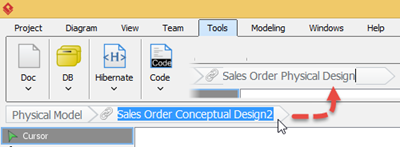
Rename newly generated ERD to Sales Order Physical Design
- To confirm the newly generated ERD is in physical mode, you can right click on the blank area of the diagram to see the diagram type under the Data Model.
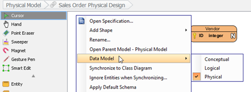
Diagram popup menu showing its a physical ERD
- Now we can start to redefine the physical model for our application.
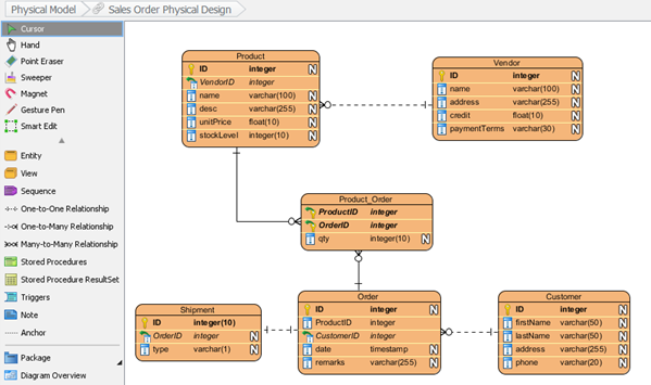
The completed physical ERD
Tracing the origin
You can always trace back the origin in your physical ERD. To do this, you can simply click on the entity you would like to look back, and press on the Transitor resource icon.
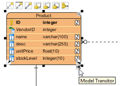
Model transitor resource icon
Select Transit From in the popup menu, and you will see Sales Order Conceptual Design.Product listed as the origin.
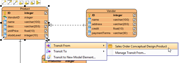
Transit back to conceptual ERD
Click on it will bring you back Product entity in the conceptual ERD.
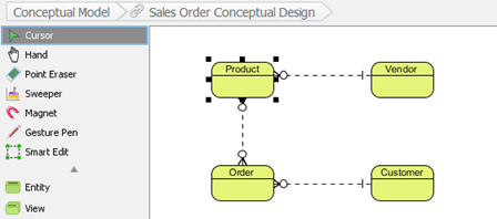
Transit back to conceptual ERD
You can do the same in the conceptual ERD, but simply change to select the Transit To popup menu. Besides using resource icon, the Transit From/To also can be found under the Related Elements section of entity’s popup menu.
Watch this Knowhow on YouTube
Here is the video version of this Knowhow
Related Know-how |
Related Links |
Is which edition is this feature available? I have a $15 subscription for the modeler edition and there is no “Transit to logical ERD” or “Transit to physical ERD” option 🙁
Hi Motig,
Thank you for asking. The Transitor feature is available in Standard Edition (or higher). Since you are using Modeler Edition, you do not see the popup menu there. BTW, just to correct that the subscription fee of Modeler Edition is USD $5, not USD $15. 🙂