

Integrate Content into Word Documents with Doc. Composer
If you want to insert project details (e.g. images, element details) into an existing Word document, use Doc. Composer’s ‘Fill-in Doc’ mode.
Doc. Composer features two modes – Build from Scratch and Fill-in Doc. Typically, a project documentation or report is a combination of background information like project goal, scope and constraints, and design details like use case details, database design, process design, etc. The Fill-in Doc mode of Doc. Composer is designed to help you “fill-in” the design details of your documentation.
Doc. Composer processes special pieces of text called Doc Fields in your document, and substitute them with actual model details. You don’t need to perform any diagram exporting or copy-and-paste. All you need to do is to write a short query statement in your document. The rest will be taken care by Doc. Composer. As an overview, “Fill-in Doc” works in this way:
- You write your project documentation in Microsoft Word.
- Place some special fields to the parts that requires the insertion of design details.
- Load the document into Doc. Composer.
- Export a document. Doc. Composer analyze the special fields in your document and replace them with actual project content.
In this article we will show you how to use the Fill-in Doc mode of Doc. Composer to develop a software requirements specification.
Overview
Here is an outline of what will be covered in this article:
- Writing Doc Base
- Opening Doc Base in Doc. Composer
- Generating document in Doc. Composer
In order to complete this tutorial, you must have the following software installed:
- Visual Paradigm 13.0 or higher
- Microsoft Word 2007 or higher
Writing Doc Base
A Doc Base is a semi-completed version of your project documentation or report. It contains only background information like introduction, project vision and objective. The design details are leave empty and be filled by Doc. Composer. Doc Base provides a base for documentation production. You provide such a base to Doc. Composer and then Doc. Composer fill the empty parts for you by embedding model data extracted from your Visual Paradigm project into your document.
- Download OSP-Software-Requirements-Specification.docx.
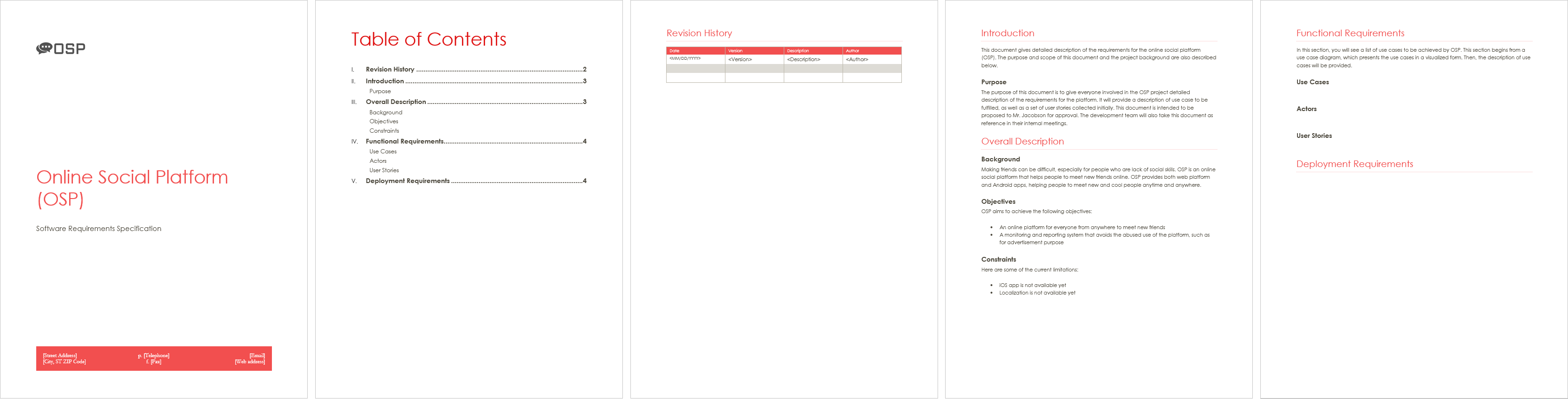
- Open the downloaded file in Microsoft Word and take a look. This document is a simple, incomplete Doc Base of software requirements specification. It contains a cover page, a table of contents, a table of revision history, and a page of background information like the introduction and project description. What you need to do now is to complete the specification by writing the necessary Doc Fields to retrieve data from a Visual Paradigm project.
Document overview
- Open Page 5 of the document. Under the Functional Requirements section there are three sub-sections – Use Cases, Actors and User Stories. Let’s fill them in one by one. Now, enter the following text under the header Use Cases:
${DIAGRAM, "Use Case Diagrams", "UseCaseDiagram", LoopInProject, "Basic"}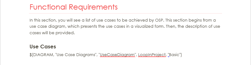
Doc Field written to query diagram
What you just entered is what we called a Doc Field. A Doc Field is a special piece of text within a Doc Base. Doc Fields will be replaced by your actual project content when being processed by Doc. Composer during document generation.
A typical Doc Field is written in this format: ${FIELD_NAME, list_of_parameters}. Below is a description of the different parts of this Doc Field:
${DIAGRAM,…} – This is a ${DIAGRAM} field for querying diagram details.
“Use Case Diagram” – Name of this Doc Field.
“UseCaseDiagram” – The type of diagram to query.
LoopInProject – To query diagrams, in this case use case diagrams, from project.
“Basic” – What to show there when a diagram is found. “Basic” means to output content base on the “Basic” element template. If you want to show the name of diagram you will replace “Basic” with “PROPERTY=name”. - Create a new line by pressing Enter.
- Let’s create a table that lists out the use cases in the project. Create a table with two rows and apply a style to it to make it looks more stylish.
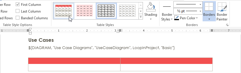
Create table
- Enter Use Case and Description in two table cells of the first row.

Table header entered
- Click on the first cell of the second row and enter the following Doc Field.
${ELEMENT, "Use Cases", "UseCase", LoopInProject, PROPERTY=name}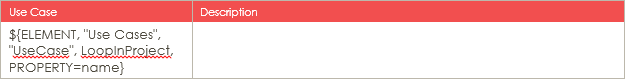
Doc Field entered in table cell
The row that contains Doc Field will replicate itself to list out all the elements queried. So you can imagine, there will be a number of rows appended to this table, with each one showing the name of a specific use case.
- In the next table cell, enter the following Doc Field:
${PROPERTY, "description"}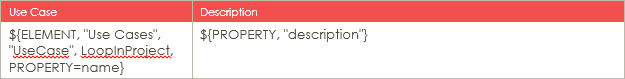
Doc Field entered in table cell
This means that for each row of use case, show the description of that use case on the second cell.
- That’s all for the Use Cases section. Let’s move on to the Actors section by creating a table of actors. Similar to what you did above, create a table with two columns and name the headers Actor and Description.
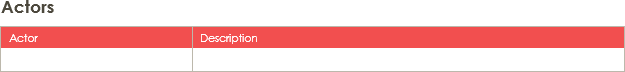
Actors table created
- Add Doc Fields to the second row. Because we want to lists out actors in this table, name the Doc Field Actors and make it query Actor instead of UseCase.
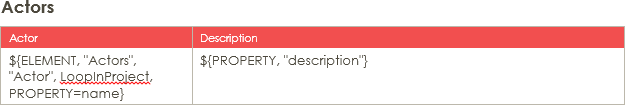
Doc Fields added to table
- Let’s continue to the User Stories section. Create a table like this:This table will list out all the user stories in the project.
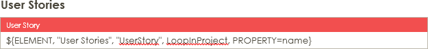
User Stories table created
- Finally, let’s write a Doc Field under the Deployment Requirements section to show a Deployment Diagram. Of course you can write a Doc Field similar to the one you wrote in step 3, but as a tutorial let’s try something different. Now, write this:
${DIAGRAM, "Deployment Plan", "DeploymentDiagram", One, "Basic"}
Deployment Diagram Doc Field
Instead of querying all Deployment Diagrams in project, this Doc Field will just query one specific Deployment Diagram in project. The diagram to query will be selected by the person who use this Doc Base to produce document and we will go into detail in the next section. Note that instead of One you can enter Any, which allows the querying of multiple diagrams from a project.
- Save the changes.
Opening Doc Base in Doc. Composer
You have finished writing a Doc Base. In this section, you will open the Doc Base in Doc. Composer and touch-up the document to be generated.
- Download Social-Networking-Service.zip.
- Unzip the downloaded file to obtain the .vpp project file.
- Open the file in Visual Paradigm. Make sure the .vux file is placed alongside with the .vpp file
- Let’s take a quick look at what we have inside this project. Open the Project Browser by selecting View > Project Browser from the application toolbar. In this project, there is one Use Case Diagram and three Deployment Diagrams.
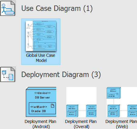
Project content
- This project also contains a number of user stories. Let’s open UeXceler to take a look. Open UeXceler by selecting UeXceler > UeXceler from the application toolbar. The user stories are listed under the User Story tab.
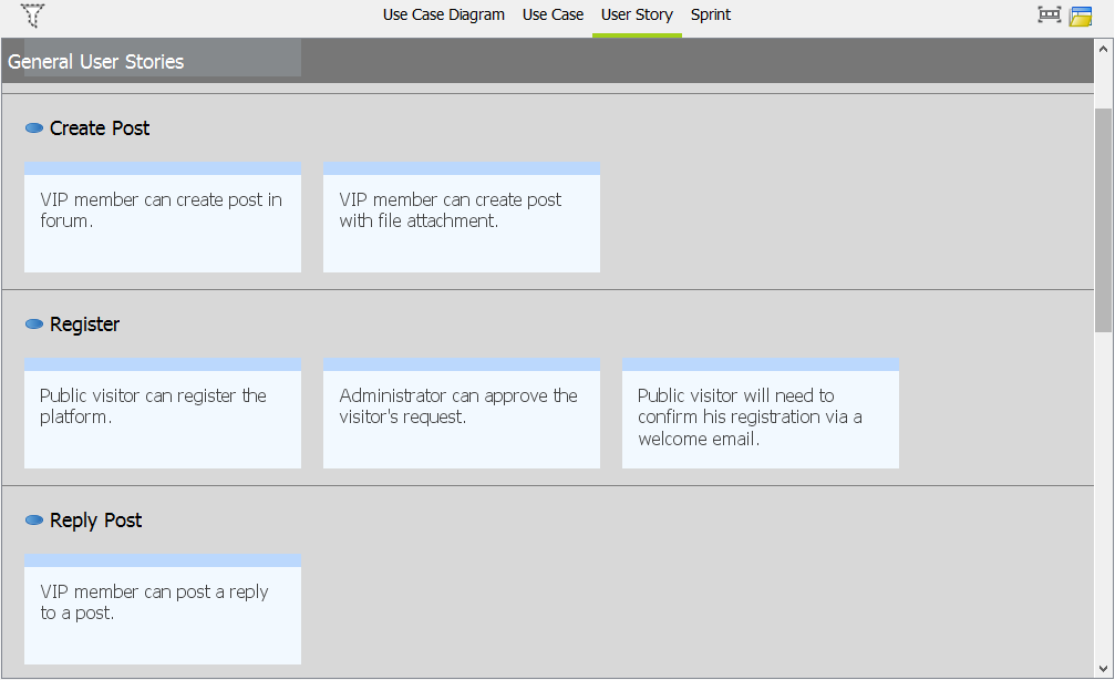
User stories in project
- Let’s create a document. Select Tools > Doc. Composer from the application toolbar.
- Click Fill-in Doc.
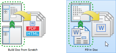
Select Fill-in Doc
- Specify the Doc Base to use in document production. Doc base is a Word document file that contains both manually written content (e.g. Introduction, project scope, etc) and Doc Fields. There are two approaches from which Doc Base can be created from. One is to create from an external document file. If you take this approach, click Choose from Local Drive and then select the document file (*.docx). Another approach is to duplicate from an existing Doc Template. If you take this approach, select the Doc Template from the template list and click OK. You will then be prompted to save a copy of the Doc Template to your computer as Doc Base. Visual Paradigm provides three default templates for you to choose from. If your team uses Teamwork Server or VPository.com, you can create your own set of templates and share them among the team.For now, click Choose from Local Drive.
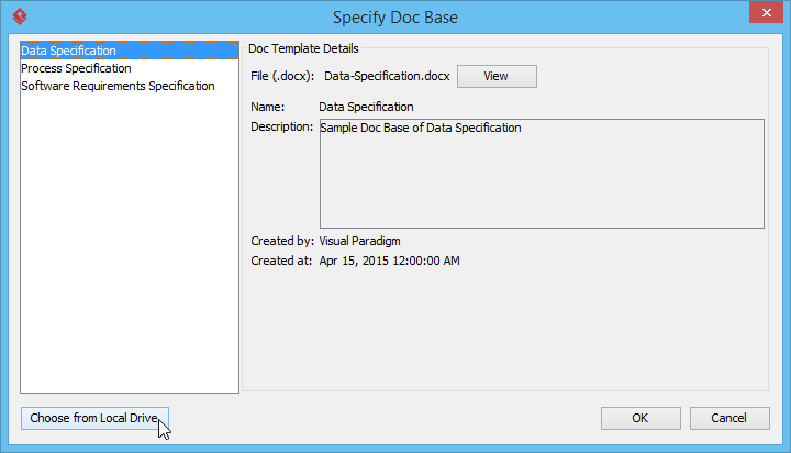
Choose Doc Base from Local Drive
- Select the document file edited in the previous section.
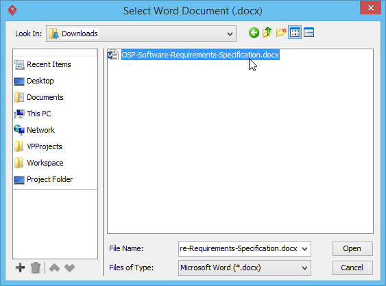
Select document file
Doc. Composer analyzes your Doc Base and presents the Doc Fields that exist in your document. Your screen should look like this:
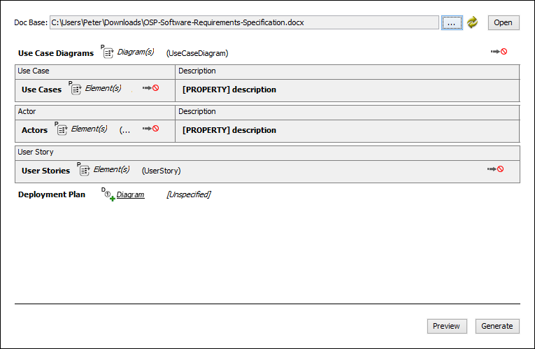
Doc. Composer screen
- Remember we have written a Doc Field that requires the selection of Deployment Diagram? It’s time to select the diagram now. Click on the Diagram link next to Deployment Plan.
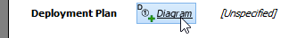
Select Deployment Diagram
- In the popup window, select the diagram Deployment Plan (Android), and then click OK.
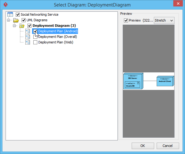
Selecting Deployment Diagram
Generating document
You are ready for producing the final document. Click Generate at the bottom right corner of Doc. Composer. Enter the filename of the document and confirm. A complete document file will then be generated, like this:
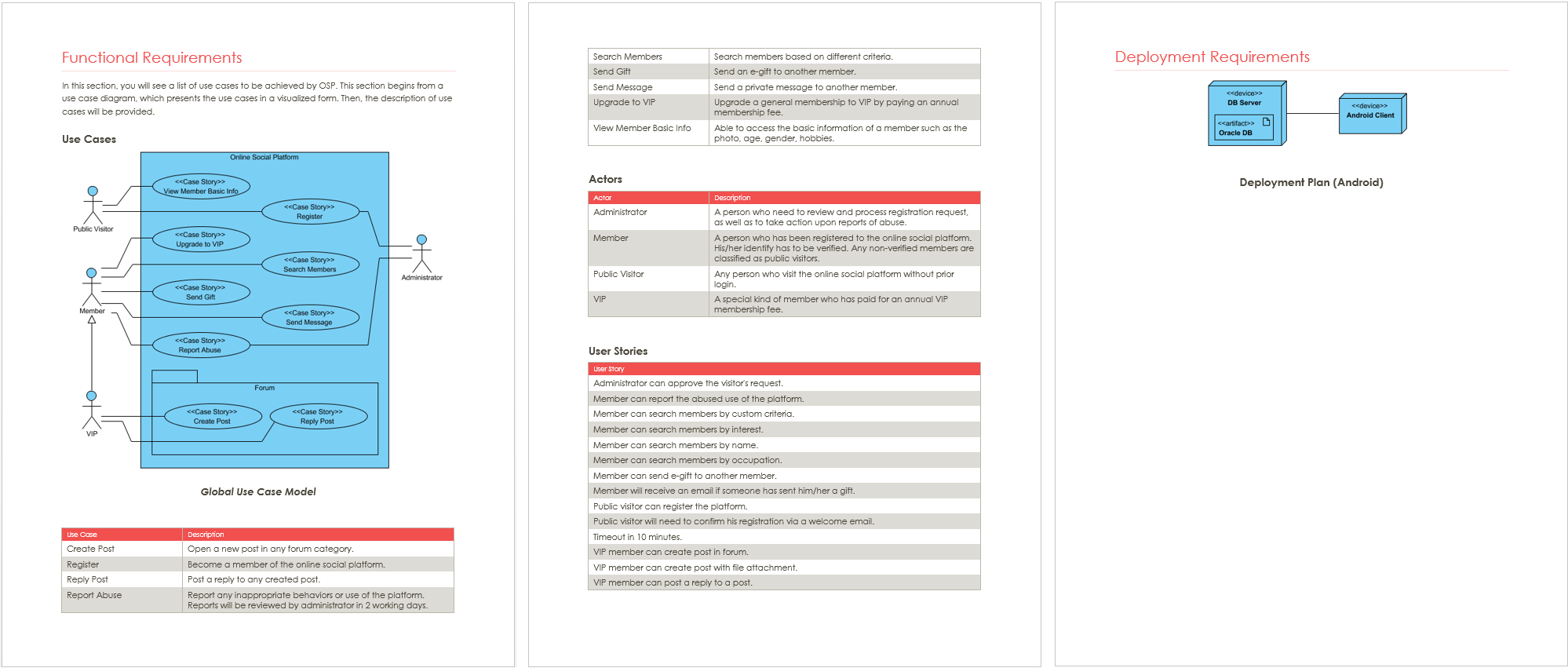
Generated Document
As you can see the Doc Fields are substituted by diagrams and model specification. The table rows have replicated themselves to lists out all the content required by the Doc Fields.
Finally, update the table of contents to make it reflect the real locations of generated contents.
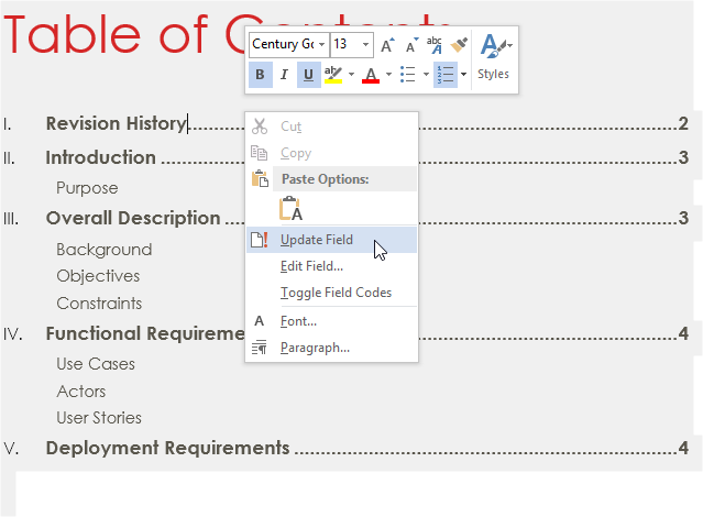
Update Table of Contents
Leave a Reply
Want to join the discussion?Feel free to contribute!