Create Protocol State Machine using Open API
 The Protocol State Machine in Unified Modeling Language (UML) helps to express the usage protocol or lifecycle of classifiers. It shows which operations are available for the classifier under which state and conditions, thus provide call sequence of the classifier’s operation. Instead of manually create the protocol state machine, you can also generate it via Visual Paradigm’s Open API. In this article we will show you how to create protocol state machine with Open API.
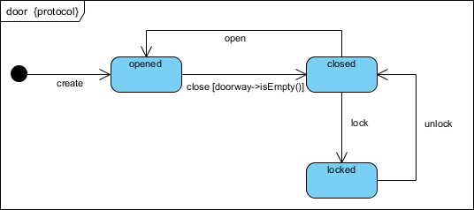
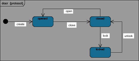
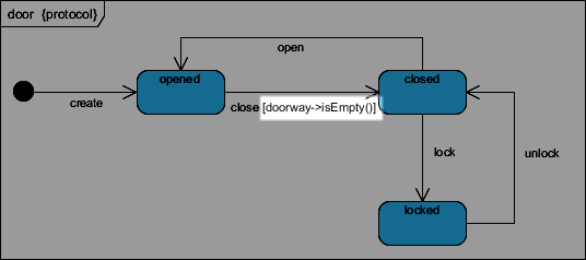
This is the protocol state machine we are going to create. It consist of 1 initial state, 3 states and 5 transitions. Each transition having a call trigger and one of the transition also with guard condition defined.
Create Blank Protocol State Diagram
Let’s start by create a blank diagram. We can use the DiagramManager.createDiagram operation to create a blank new diagram.
DiagramManager diagramManager = ApplicationManager.instance().getDiagramManager();
IStateDiagramUIModel diagram = (IStateDiagramUIModel) diagramManager.createDiagram(IDiagramTypeConstants.DIAGRAM_TYPE_STATE_DIAGRAM);
// name the diagram as "door"
diagram.setName("door");
// specify the diagram as Protocol State Machine
diagram.setProtocolStateMachine(true);
Create the Class for our Protocol State Machine
When the diagram is ready we can create the class and use it as the classifier of the protocol state machine.
// create "Door" class as the classifier of the protocol state machine
IClass doorClassModel = IModelElementFactory.instance().createClass();
doorClassModel.setName("Door");
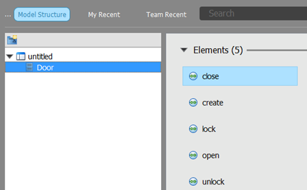
After the class being created, we then create several operations in the class which will be in the state machine.
// define operations for the Door class
IOperation opsCreate = doorClassModel.createOperation();
opsCreate.setName("create");
opsCreate.setVisibility(IOperation.VISIBILITY_PRIVATE);
Repeat the steps above to create the open, close, lock and unlock operations.
Finally we specify the protocol state machine as the sub-diagram of the class.
// specify the protocol state machine as sub-diagram of Door class
doorClassModel.addSubDiagram(diagram);
Create Initial Pseudo State
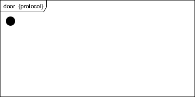
Once the classifier was created we then start to create the content of our diagram. We starting from the initial pseudo state.
// create initial pseudo state model
IInitialPseudoState initialState1Model = IModelElementFactory.instance().createInitialPseudoState();
// create shape for initial pseudo state
IInitialPseudoStateUIModel initialState1Shape = (IInitialPseudoStateUIModel) diagramManager.createDiagramElement(diagram, initialState1Model);
// specify its location and size
initialState1Shape.setBounds(22, 81, 20, 20);
Next we move on to create the states.
Create States
To create the states:
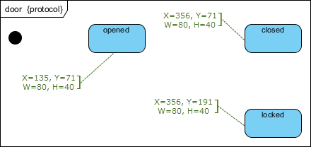
// create model for "opened" state
IState2 stateOpenedModel = IModelElementFactory.instance().createState2();
stateOpenedModel.setName("opened");
// create shape for "opened" state
IState2UIModel stateOpenedShape = (IState2UIModel) diagramManager.createDiagramElement(diagram, stateOpenedModel);
// specify its location and size
stateOpenedShape.setBounds(135, 71, 80, 40);
// set to automatic calculate the initial caption position
stateOpenedShape.setRequestResetCaption(true);
Now let’s try to create the other states in the diagram.
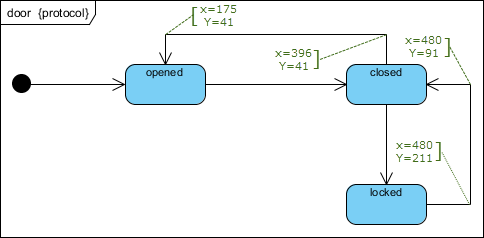
Create Transition
After the states are being created, we can then start to create the transitions. To create the transition:
// create transition model between initial state and opened state
ITransition2 tranInitialOpenedModel = IModelElementFactory.instance().createTransition2();
// specify the from end as the initial state, and the to end is opened state
tranInitialOpenedModel.setFrom(initialState1Model);
tranInitialOpenedModel.setTo(stateOpenedModel);
// create connector into diagram
ITransition2UIModel tranInitialOpenedShape = (ITransition2UIModel) diagramManager.createConnector(diagram, tranInitialOpenedModel, initialState1Shape, stateOpenedShape, null);
tranInitialOpenedShape.setRequestResetCaption(true);
Create Call Trigger for the Transition
All transitions in our model do have call trigger to indicate the event where the transition being fired. To create the call trigger:
// create call trigger
ICallTrigger callTriggerCreateModel = IModelElementFactory.instance().createCallTrigger();
callTriggerCreateModel.setName("create");
// specify the operation for the call trigger
callTriggerCreateModel.setOperation(opsLock);
// add call trigger to transition
tranInitialOpenedModel.addTrigger(callTriggerCreateModel);
Repeat the steps above to create the call triggers for the rest of the transitions.
Create Guard Condition for the Transition
As in the diagram show in the beginning of the article, the transition from opened to closed state do have a guard condition defined. To create the guard condition:
// create constraint element as the guard condition
IConstraintElement guard = IModelElementFactory.instance().createConstraintElement();
// specify the detail of the guard condition
guard.setName("doorway->isEmpty()");
// set the guard condition into transition
tranOpenedClosedModel.setGuard(guard);
Show up the diagram
When everything is ready we can show up the diagram.
diagramManager.openDiagram(diagram)
Sample Plugin
The sample plugin attached in this article demonstrate how to create state diagram using Open API. After you deploy the plugin into Visual Paradigm, you can then click the plugin button in the application toolbar to trigger it.
Download Sample Plugin
You can click this link to download the sample plugin.
Related Know-how |
Related Link |




Leave a Reply
Want to join the discussion?Feel free to contribute!