Create State Diagram using Open API
 State Diagram, also call State Machine Diagram is one of the most important diagram in Unified Modeling Language. It helps to visualize the state change of a system, or a particular object in response to various events during the execution of the software. Besides create state diagrams manually, you an also create it programmatically using Open API. In this article we will show you how to create the state diagram with Visual Paradigm’s Open API.
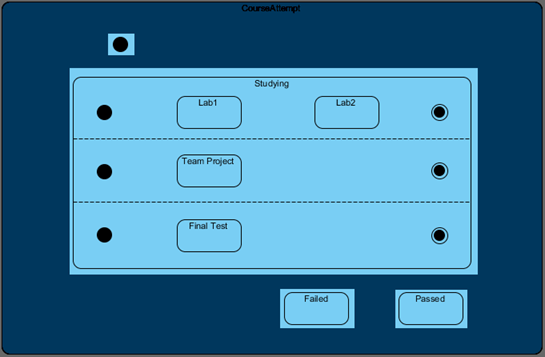
This is the state diagram which we are going to create. The diagram consists of 8 states, 4 regions, 4 initial pseudo states, 3 final states and 10 transitions. Let’s start by create a blank state diagram.
Create Blank State Diagram
Let’s start by create a blank diagram. We can use the DiagramManager.createDiagram operation to create a blank new diagram.
DiagramManager diagramManager = ApplicationManager.instance().getDiagramManager();
IStateDiagramUIModel diagram = (IStateDiagramUIModel) diagramManager.createDiagram(IDiagramTypeConstants.DIAGRAM_TYPE_STATE_DIAGRAM);
Create States
Once the diagram is created, we can then move on to create the diagram elements and model elements. To create the state:
// create model for CourseAttempt state
IState2 stateCourseAttemptModel = IModelElementFactory.instance().createState2();
stateCourseAttemptModel.setName("CourseAttempt");
// create shape for CourseAttempt state
IState2UIModel stateCourseAttemptShape = (IState2UIModel) diagramManager.createDiagramElement(diagram, stateCourseAttemptModel);
// specify its location and size
stateCourseAttemptShape.setBounds(181, 23, 675, 440);
// specify the region are on horizontal direction
stateCourseAttemptShape.setRegionOrientation(IState2UIModel.RO_HORIZONTAL);
// set to automatic calculate the initial caption position
stateCourseAttemptShape.setRequestResetCaption(true);
Unlike most of the model types, state require region for containing child elements. Let’s move to create the region inside the CourseAttempt state.
Add Region to States
The region is so visible (especially when the state have only one region), but it is necessary for making a state able to contain child elements. To create the region:
// create region model under CourseAttempt state model
IRegion stateCourseAttemptRegionModel = stateCourseAttemptModel.createRegion();
// create region shape under CourseAttempt state
IRegionUIModel stateCourseAttemptRegionShape = (IRegionUIModel) diagramManager.createDiagramElement(diagram, stateCourseAttemptRegionModel);
stateCourseAttemptRegionShape.setBounds(181, 38, 675, 425);
// add region shape to CourseAppempt in diagram
stateCourseAttemptShape.addChild(stateCourseAttemptRegionShape);
Now we are ready to create the child elements such as other states, initial pseudo states and final states inside the region.
Create Elements inside Region
You already know how to create the states, and now we will show you how to create the initial pseudo states and final states. We start from the initial pseudo states.
// create initial pseudo state model
IInitialPseudoState initialState1Model = IModelElementFactory.instance().createInitialPseudoState();
// add the initial pseudo state to child of region under CourseAttempt state
stateCourseAttemptRegionModel.addChild(initialState1Model);
// create shape for initial pseudo state
IInitialPseudoStateUIModel initialState1Shape = (IInitialPseudoStateUIModel) diagramManager.createDiagramElement(diagram, initialState1Model);
initialState1Shape.setBounds(320, 67, 20, 20);
// add initial pseudo state as child of region under CourseAttempt state
stateCourseAttemptRegionShape.addChild(initialState1Shape);
Next we can move to create the Studying state. Try to use what you have learn to create Studying state, including its nested regions, initial pseudo states and nested states.
After that we can move to create the final state. To create final state:
IFinalState2 finalState1Model = IModelElementFactory.instance().createFinalState2();
studyingRegion1Model.addChild(finalState1Model);
IFinalState2UIModel finalState1Shape = (IFinalState2UIModel) diagramManager.createDiagramElement(diagram, finalState1Model);
finalState1Shape.setBounds(718, 151, 20, 20);
studyingRegion1Shape.addChild(finalState1Shape);
Again, time for your turn to create the other 2 final states.
Create Transitions between States
It’s almost done. We can start to create the transitions between elements. To create transition:
// create transition model between initial state and Studying state
ITransition2 tranInitialStudyingModel = IModelElementFactory.instance().createTransition2();
// specify the from end as the initial state, and the to end is Studying state
tranInitialStudyingModel.setFrom(initialState1Model);
tranInitialStudyingModel.setTo(stateStudyingModel);
// create connector into diagram
diagramManager.createConnector(diagram, tranInitialStudyingModel, initialState1Shape, stateStudyingShape, null);
Try to repeat the above and create the rest of the transitions.
Show up the diagram
When everything is ready we can show up the diagram.
diagramManager.openDiagram(diagram);
Sample Plugin
The sample plugin attached in this article demonstrate how to create state diagram using Open API. After you deploy the plugin into Visual Paradigm, you can then click the plugin button in the application toolbar to trigger it.
Download Sample Plugin
You can click this link to download the sample plugin.
Related Know-how |
Related Link |


Leave a Reply
Want to join the discussion?Feel free to contribute!