Create Use Case Diagram using Open API
![]() Use Case Diagram in Unified Modeling Language is a great tool in requirement analysis. It gives user a visual presentation about the users of the system as well as the functions they are interested in order to achieve a “goal”. Instead of creating use case diagram manually, you can also create it programmatically using Open API. In this article we will show you how to create use case diagram with Visual Paradigm’s Open API.
Use Case Diagram in Unified Modeling Language is a great tool in requirement analysis. It gives user a visual presentation about the users of the system as well as the functions they are interested in order to achieve a “goal”. Instead of creating use case diagram manually, you can also create it programmatically using Open API. In this article we will show you how to create use case diagram with Visual Paradigm’s Open API.
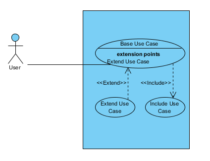
This is the use case diagram which we are going to create. The diagram consists of an actor, a system boundary, 3 use cases, and 3 popular relationships on use case diagram, association, include and extend. Let’s start with create a blank use case diagram.
Create Blank Use Case Diagram
We can use the DiagramManager.createDiagram operation to create a blank new diagram.
DiagramManager diagramManager = ApplicationManager.instance().getDiagramManager();
IUseCaseDiagramUIModel diagram = (IUseCaseDiagramUIModel) diagramManager.createDiagram(DiagramManager.DIAGRAM_TYPE_USE_CASE_DIAGRAM);
Creating Diagram and Model Elements
Once the diagram is created, we can then move on to create the diagram elements and model elements. Our diagram include an actor, a system boundary which containing 3 use cases. Creating model elements involve the 4 major steps:
- Creating object instance of the model element
- Specify the properties of the model element, i.e. name, description, etc…
- Create shape instance of the model element
- Specify the properties of the shape, i.e. location, color, etc…
We first create the actor and system boundary. To create actor:
// Step 1: create object instance using IModelElementFactory
IActor actorModel = IModelElementFactory.instance().createActor();
// Step 2: specify properties of model element
actorModel.setName("User");
// Step 3: create shape instance using DiagramManager
IActorUIModel actorUI = (IActorUIModel) diagramManager.createDiagramElement(diagram, actorModel);
// Step 4: specify properties of the shape
actorUI.setBounds(126, 179, 30, 60); // specify its position on diagram
actorUI.getCaptionUIModel().setBounds(115, 239, 50, 15); // specify position for the actor caption
Now the actor is created, and we can use the similar approach to create system boundary.
ISystem systemModel = IModelElementFactory.instance().createSystem();
systemModel.setName("Demo system");
ISystemUIModel systemUI = (ISystemUIModel) diagramManager.createDiagramElement(diagram, systemModel);
systemUI.setBounds(277, 132, 216, 280);
Next we can move on to create the use cases. Basically the steps for create use case is pretty similar to create of actor and system boundary. The only different is the use cases are the child of the system boundary, and therefore we need to add them as the child of system boundary.
// create base use case
IUseCase baseUseCaseModel = IModelElementFactory.instance().createUseCase();
baseUseCaseModel.setName("Base Use Case");
systemModel.addChild(baseUseCaseModel); // add base use case as child of the system boundary
IUseCaseUIModel baseUseCaseUI = (IUseCaseUIModel) diagramManager.createDiagramElement(diagram, baseUseCaseModel);
// add base use case as child of system boundary
systemUI.addChild(baseUseCaseUI);
baseUseCaseUI.setBounds(302, 189, 181, 59); // create extended use case
IUseCase extendUseCaseModel = IModelElementFactory.instance().createUseCase();
extendUseCaseModel.setName("Extend Use Case");
systemModel.addChild(extendUseCaseModel);
IUseCaseUIModel extendUseCaseUI = (IUseCaseUIModel) diagramManager.createDiagramElement(diagram, extendUseCaseModel);
// add extended use case as child of system boundary
systemUI.addChild(extendUseCaseUI);
extendUseCaseUI.setBounds(302, 307, 80, 40);// create include use case
IUseCase includeUseCaseModel = IModelElementFactory.instance().createUseCase();
includeUseCaseModel.setName("Include Use Case");
systemModel.addChild(includeUseCaseModel);
IUseCaseUIModel includeUseCaseUI = (IUseCaseUIModel) diagramManager.createDiagramElement(diagram, includeUseCaseModel);
// add include use case as child of system boundary
systemUI.addChild(includeUseCaseUI);
includeUseCaseUI.setBounds(403, 307, 80, 40);
Creating Relationships
In our example we have 3 relationships, the association between Actor and Base Use Case, include relationship between Base Use Case and Include Use Case, and the extend relationship between Base Use Case and Extend Use Case. Let’s walk through it one by one. Creating relationships basically have the following steps:
- Create relationship model
- Specify the properties of the relationship model, i.e. name, description, etc…
- Specify the model element of From end and To end
- Create relationship connector (view)
- Specify the properties of the connector, i.e. caption position, color, etc…
To create the association between Actor and Base Use Case:
// create association model between actor and base use case
IAssociation associationModel = IModelElementFactory.instance().createAssociation();
associationModel.setFrom(actorModel);
associationModel.setTo(baseUseCaseModel);
// create association connector
IAssociationUIModel associationUI = (IAssociationUIModel) diagramManager.createConnector(diagram, associationModel, actorUI, baseUseCaseUI, null);
Next we move on to create include and extend relationship. The steps for create include and extend relationship is pretty similar with association.
// create include relationship between base use case and include use case
IInclude includeModel = IModelElementFactory.instance().createInclude();
includeModel.setFrom(baseUseCaseModel);
includeModel.setTo(includeUseCaseModel);
// create include connector
IIncludeUIModel includeUI = (IIncludeUIModel) diagramManager.createConnector(diagram, includeModel, baseUseCaseUI, includeUseCaseUI, null);
includeUI.getCaptionUIModel().setBounds(385, 270, 82, 14); // specify position for the include caption// create extend relationship between base use case and extend use case
IExtend extendModel = IModelElementFactory.instance().createExtend();
extendModel.setFrom(baseUseCaseModel);
extendModel.setTo(extendUseCaseModel);
// create extend connector
IExtendUIModel extendUI = (IExtendUIModel) diagramManager.createConnector(diagram, extendModel, baseUseCaseUI, extendUseCaseUI, null);
extendUI.getCaptionUIModel().setBounds(295, 270, 80, 15); // specify position for the extend caption
For the extend relationship we can specify a specific extension point where the extension relays on. To create extension point:
IExtensionPoint extensionPoint = IModelElementFactory.instance().createExtensionPoint();
extensionPoint.setName("Extend Use Case");
extendModel.setExtensionPoint(extensionPoint); // specify extension point for the extend relationship
Finally we show up the diagram
diagramManager.openDiagram(diagram);
Sample Plugin
The sample plugin attached in this article demonstrate how to create use case diagram using Open API. After you deploy the plugin into Visual Paradigm, you can then click the plugin button in the application toolbar to trigger it.
Download Sample Plugin
You can click this link to download the sample plugin.
Related Know-how |
Related Links |


Leave a Reply
Want to join the discussion?Feel free to contribute!