How to Simulate UI Navigation
During UI design, having screen mock-ups could give others a better idea as to what users would be looking at when interacting with the system. With Visual Paradigm’s products ( e.g. Visual Paradigm for UML), you can create mock-ups using user interface diagrams. Apart from static visual presentation, you may also simulate navigation between screens after publishing your project to HTML files.
In this article, we are going to show you how to simulate UI navigation using Visual Paradigm for UML (VP-UML) Enterprise Edition. We will create a few screen mock-ups and publish your project, after which you can see dynamic user interaction between screen shots in a web browser.
As an example, let’s say we are designing a UI which authenticates users and upon successful login, allows them to select orders for review and finally process them.
Steps to Create User Interface Diagrams
In our example, we will create a total of 5 user interface diagrams for screen mock-ups.
Steps to Create the Login Screen
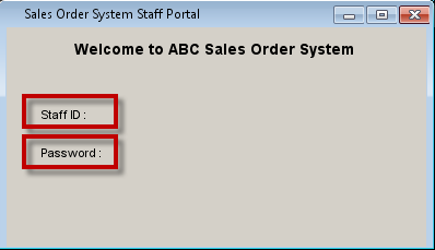
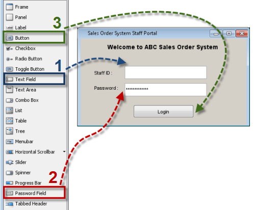
This is what we are going to mock up in the 1st diagram. It is a login screen for user authentication.
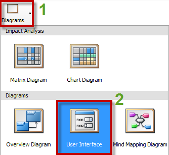
- To add a new user interface diagram, select Diagrams > User Interface from the main toolbar.
- To rename your diagram, right click on the background of your diagram and select Rename…
Name the diagram U01 Login. (Note: This is our 1st diagram.)
- From the Diagram Toolbar, select Frame and add one to the diagram. Double click at the top of the frame to name it Sales Order System Staff Portal.
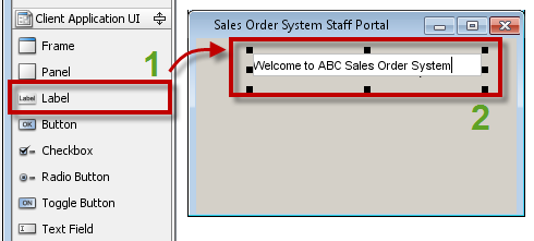
- From the Diagram Toolbar, select label and add one to the frame. Name it Welcome to ABC Sales Order System.
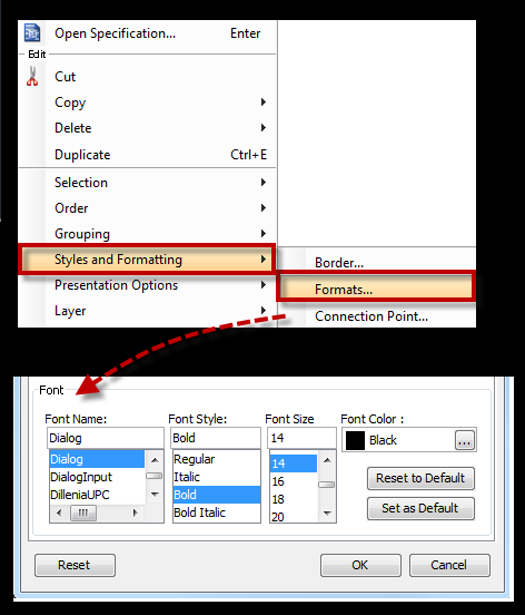
To format the text, right click on the label and select Styles and Formatting > Formats…
In the dialog, go to the Font section and change it as you like.
- Add two more labels, Staff ID : and Password :
- Add a Text Field next to Staff ID. Add a Password Field next to Password. Add a button and name it Login.
Steps to Create the Order Main Screen
This is what we are going to mock up in the 2nd diagram.
- Add a new user interface diagram and name it U02 Order Main Screen. This is our 2nd diagram.
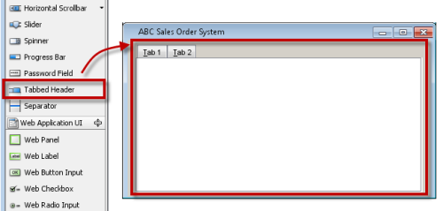
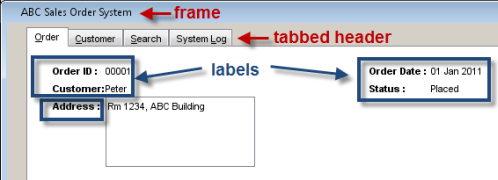
- In U02 Order Main Screen, add a frame and name it ABC Sales Order System.
- Add a Tabbed Header to the frame.
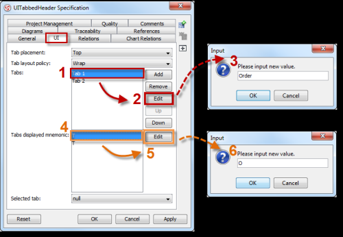
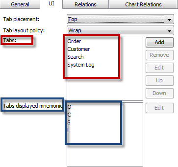
- Right click on the tabbed header and select Open Specification… Note: In a fresh tabbed header, there are 2 default tabs called Tab 1 and Tab 2. In the UITabbedHeader Specification dialog, the tab list corresponds to the mnemonic character list below, which ultimately corresponds to the UI displaying these tabs in the same order, but from left to right visually. By default, the first character of a tab name (e.g. Tab 1 –> T ) becomes its mnemonic character (unless you change it). In the UITabbedHeader Specification dialog, select the UI tab.Select Tab 1. Click Edit. Name it Order.Select T (first item in the list). Click Edit. Enter the letter O.Edit Tab 2. Name it Customer. Change the mnemonic character to the letter C.
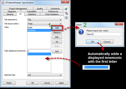
- Click Add to append a new tab to the list and name it Search.
- Click Add to insert another tab and name it System Log. Change the mnemonic character to L as the default S has already been taken by the Search tab.
- Add a text label and name it Order Status :
- Add a combo box next to the label Order Status.
To add items, right click on the combo box and select Open Specification…
In the dialog, click Add to add these 5 items [All, Quoted, Invoiced, Placed, Done] one by one. Then choose “All” to be the selected (or default) item.
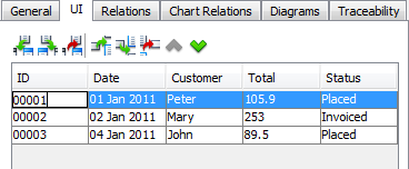
- Add a table below the label Order Status.
Right click on the table and select Open Specification…
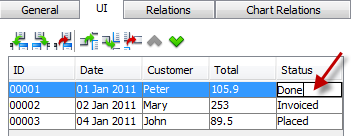
In the dialog (under the UI tab), click the Insert Column to Right button and add these 5 columns one by one [ ID, Date, Customer, Total, Status ].
Click the Insert Row Below button to add 3 rows to the table.
To populate the table, double click on each cell to enter the values as shown.
Steps to Create the Order Details Screen
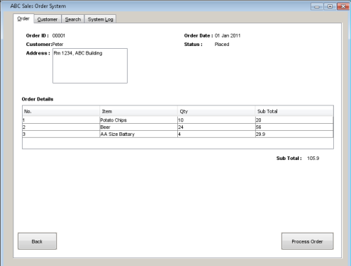
This is what we are going to mock up in the 3rd diagram.
- Add a new user interface diagram and name it U03 Order Details. This is our 3rd diagram.
- Add a frame.
- Add a tabbed header.
- In the upper screen, add labels.
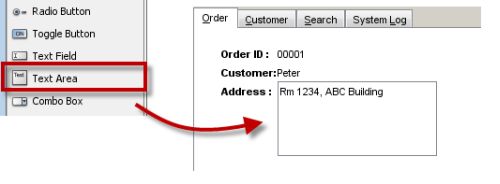
- Add a text area [Rm 1234, ABC Building]
- In the screen’s middle, add a table (4 columns X 3 rows).
- Add labels.
- Add 2 buttons at the screen’s bottom.
Steps to Create the Order Details Screen (After the Order Being Processed)
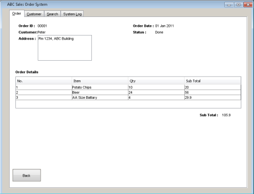
This is what we are going to mock up in the 4th diagram.
Since diagram 4 is very similar to diagram 3, we can make a copy of diagram 3 first and then edit from there. This will save us a lot of work.
- Add a new user interface diagram and name it U04 Order Processed.
- Go to diagram 3 (U03 Order Details). Click on the top of the frame. Press Ctrl-C to copy.
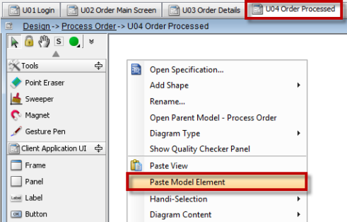
- To paste it in diagram 4 (U04 Order Processed), right click on the diagram and select Paste Model Element.
- Let’s update the order status. Double click on the label Placed. Type in Done to replace Placed.
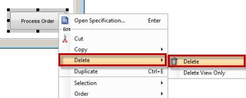
- Since this screen appears after the order has been processed, remove the Process Order button at bottom right. Right click on it and select Delete > Delete.
Steps to Create the Order Main Screen (After the Order Being Processed)
This is what we are going to mock up in the 5th diagram.
Since diagram 5 is very similar to diagram 2, we can make a copy of diagram 2 first and then edit from there. This will save us a lot of work.
- Add a new user interface diagram and name it U05 Order Main Screen (Order Completed).
- Go to the U02 Order Main Screen diagram. Click on the top of the frame. Press Ctrl-C to copy.
- To paste it in diagram 5, U05 Order Main Screen (Order Completed), right click on the diagram and select Paste Model Element.
- Right click on the table and select Open Specification…In the dialog, double click on the Status for Order ID 00001 and replace Placed with Done.
Steps to Model UI Flow
Create References to Jump to Diagrams
In this section, we’ll add references to a few components (e.g. buttons) so that clicking them would jump to the appropriate screens (represented by diagrams 2 to 5) for UI simulation.
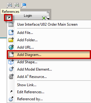
- Expected UI Navigation: Clicking the Login button will take users to diagram 2 showing the order list. To Do: Create a reference from the Login button to jump to diagram 2.Select the Login button and then click on the References icon around it.Select Add Diagram…
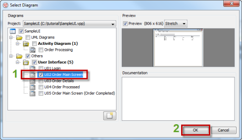
In the Select Diagram window, select U02 Order Main Screen. Click OK.
- Expected UI Navigation: Clicking on the order row ( ID 00001 ) in the order list will take users to the U03 Order Details Screenshowing details of that particular order.In the U02 Order Main Screen diagram, select the table and click on the Referencesicon.Select Add Diagram…Add a reference to the U03 Order Details Screen diagram.
- Expected UI Navigation: Clicking the Back button in U03 Order Details Screen will take users back to U02 Order Main Screen.In the U03 Order Details Screen diagram, select the Back button and click on the Referencesicon.Select Add Diagram…Add a reference to the U02 Order Main Screen diagram.
- Expected UI Navigation: Clicking the Process Order button in U03 Order Details will take users to the U04 Order Processedscreen.In the U03 Order Details diagram, select the Process Order button and click on the References icon.Select Add Diagram…Add a reference to the U04 Order Processed diagram.
- Expected UI Navigation: Clicking the Back button (after order being processed) in U04 Order Processed will take users to U05 Order Main Screen (Order Completed).In the U04 Order Processed diagram, select the Back button and click on the Referencesicon.Select Add Diagram…Add a reference to the U05 Order Main Screen (Order Completed) diagram.
Publish Your Project to Simulate UI Flow
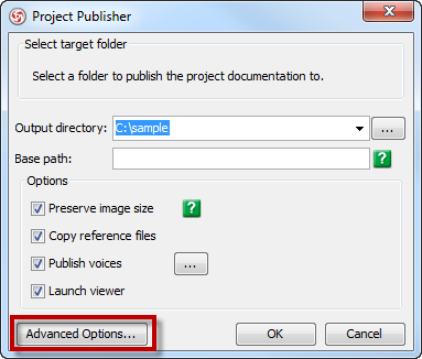
- From the menu bar, select Tools > Project Publisher…
- In the Project publisher… dialog, click Advanced Options…
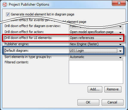
- In the Project Publisher Optionsdialog,- for Drill down effect for UI elements, select Open references– for Default diagram, select U01 Login(which is our 1st diagram). Click OK.
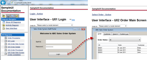
- Your published project will appear in a web browser with UI navigation simulation available. For example, if you click on the Login button, it will jump to the order main screen (U02 Order Main Screen).
You can download the sample project file here.
Remarks:
User Interface Diagram is supported by:
Drill down effect for UI elements is available with Build sp2_20110817p or later. ( how to update? )
Watch this tutorial in YouTube.











Leave a Reply
Want to join the discussion?Feel free to contribute!