How to Model Gates in UML Sequence Diagrams
To pass a message between two sequence diagrams in UML modeling, we can make use of gates. Through modeling gates, we could relate the message outside an interaction fragment with message inside another interaction fragment.
Graphically a gate, with an arrowed line, connects to the sequence diagram’s frame edge with one end and the other end connected to a lifeline.
In this tutorial we will show you how to model gates in sequence diagrams using Visual Paradigm for UML (VP-UML).
Steps to model gates
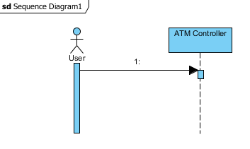
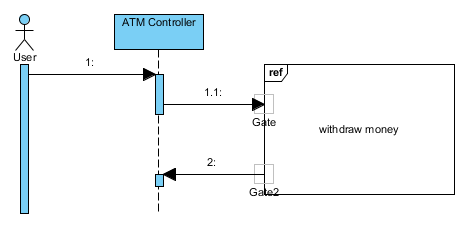
- Let’s say we have a simple sequence diagram as shown below.
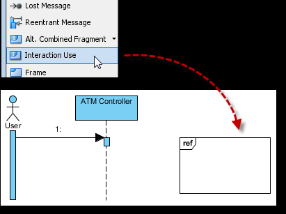
- Suppose there’s a back-end component represented by an interaction use.
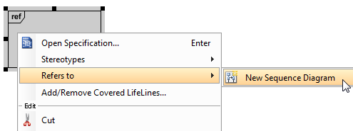
From the Diagram Toolbar, drag Interaction Use onto the sequence diagram. - Right click on the interaction use and select Refers to > New Sequence Diagram.
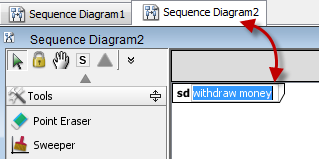
- Rename Sequence Diagram 2 to withdraw money inside the tab in the corner.
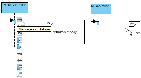
- Back in Sequence Diagram 1, drag the Message -> LifeLine icon (from ATM Controller) to withdraw money. Release your mouse when you reach the frame’s edge.
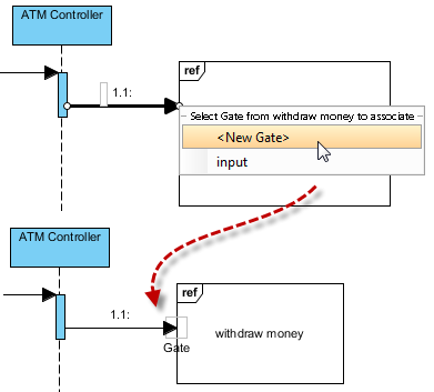
- When prompted, select <New Gate>.
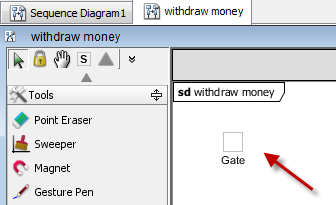
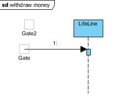
- Double click on the text “withdraw money” (inside the interaction use) to go to that sequence diagram. In it, you should see the Gate automatically inserted for what you’ve just drawn in Sequence Diagram 1.
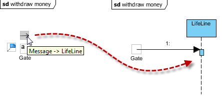
- Drag the Message -> LifeLine icon (from Gate) to the right and release mouse to create a new lifeline.
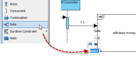
- Back in Sequence Diagram 1, add another gate. Drag Gate from the Diagram Toolbar to withdraw money (Note: You would see a letter ‘M’ displayed to indicate that it is a master view).
- If you look at the withdraw money sequence diagram, you should see Gate2 which has been automatically inserted with our new addition from the previous step.
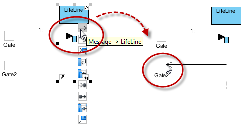
- We’ll now send a message from LifeLine back to Gate2.
Place Gate2 below Gate.
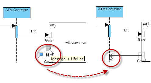
Select LifeLine and drag the Message -> LifeLine icon to the left. Release your mouse when you reach the right edge of Gate2. - Back in Sequence Diagram 1, drag the Message -> LifeLine icon backwards (from Gate2) to ATM Controller.
- You should end up with a diagram that looks something like this.
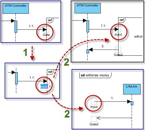
What happens if you change the label of a gate in one of the diagrams?
Gates in Sequence Diagram 1 and the withdraw money sequence diagram share the same models in repository. So changes to them will be synced across these diagrams.
For example, if you rename the top gate to “input” in Sequence Diagram 1, you’ll see that the gate in the withdraw money sequence diagram will also be renamed to “input” automatically.



Leave a Reply
Want to join the discussion?Feel free to contribute!