

Transition and Navigation with Model Transitor
A cycle in software development or process improvement is often formed by many distinct phases. For example, one may hold a meeting with end user to collect the requirements. Next, s/he thinks of the room for improvement and then documents the new idea. Furthermore, s/he discusses with the user again and finally puts the idea into practice by providing a solution.
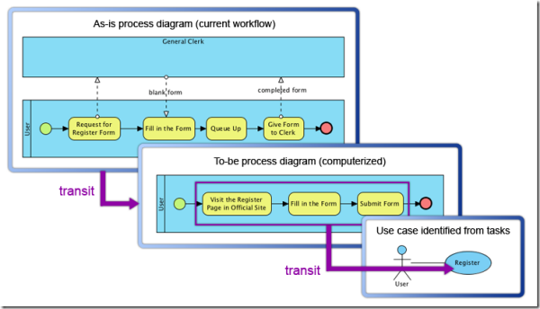
Throughout a cycle, visual modeling helps to express an idea and formalize changes. Different types of diagrams can be applied in accord with various situations. For example, business process diagram can be used to model the current process of an organization, and the improved one. Use case diagram can be used to model the features of a system at high level. Requirement diagram can be used to model user’s specific requirement. When a cycle evolves, the models will get evolved too. Take a look at the image below. The as-is process diagram is evolved into a to-be process diagram that illustrates the process to be applied in future, and the tasks in to-be process diagram are evolved into a use case in a use case diagram for modeling system level user goal. We can imagine when the model evolves in further, the use case can be transited into a set of requirement.
An overview on model transitor
Creating a transition
Diagram transition
Here we are going to see how to make use of an “as-is” business process diagram to form a “to-be” diagram, with the help of model transitor. Although business process diagram is used in this demo, the idea of diagram transition can apply in any other situations. For example, transiting a prototype object model to an implementation model, transiting a basic organization chart to a refined one.
- Right click on the source as-is diagram and select Utilities > Transit to New Diagram…from the popup menu.

To transit a as-is business process diagram
- In the Select Parent Model dialog box, create a model folder holding the “to-be” diagram to be created. Click OK to confirm.

Create a parent model for holding the new diagram
- This creates a new diagram for the “to-be” model. What? It looks exactly the same as the as-is diagram? Yes, this is true for this moment, and it’s time for you to edit the diagram to make it become a to-be model.And now, you have got a completed to-be process model. In this case, the to-be business process diagram is used to represent the registration process after the computerization of system. Therefore, you can see the pool General Clerk is no longer existing. Besides, the task Request for Register Form is renamed to Visit the Register Page in Official Site.In practice, the diagram will be far bigger, and it is difficult and unreasonable to identify the changes between as-is and to-be diagrams. Therefore, we may make use of the visual diff tool to help in identifying changes. We will talk about visual diff later on in this article.

Editing the to-be business process diagram

A completed to-be business process diagram


Model element transition
While a diagram transition refers to an advancement of model in process or stage level, you can also establish transition in model element level. For all kinds of model element, you can add “from” or “to” transition through their popup menu. In specific, for shapes like (business) task, subprocess or class, you may also create and transit to a new shapes at the same time. In this section, we will see how to create a transit to a use case from several tasks.
- Select and right click on the shapes to add a transition.

Select several tasks to create and transit to a use case
- Select Related Elements > Create Use Case. For other shapes, you won’t see the Create Use Case menu. All you need is to select Transit To/From, then Manage Transit To/From for adding transition with an existing shape.

Create a use case
- In the Create Use Case dialog box, choose the parent (model) for the use case to be created, fill in its specification. An actor will also be created and connected to the use case if the selected tasks are placed inside a lane or pool. Fill in also the information about the actor. Click OK to proceed.

Select the parent of use case and fill in its details
- Decide how to visualize the use case and actor by either putting it in a new diagram, or placing it in an existing diagram. Click Create to proceed.

A use case diagram is formed
This forms a diagram with use case and actors in it. Don’t forget the use case is transited from tasks in business process diagram.
You may probably have a question: how to trace back to the tasks? Please read the coming section for the answer.

To visualize a use case


Navigation within a transition
One of the key usage of Model Transitor is to navigate between the from and to shapes. Let’s continue with the former banking system example by navigating to tasks from use case.
- Move the mouse cursor over the use case Register.

Select the use case to navigate its transited tasks
- Click on the transitor resource at the bottom right of shape, and select Transit From, and the shape to transit to. On the contrary, if I were to navigate from task to use case, I need to select Transit To, then the use case.The business process diagram is opened with the task selected.

Navigate to a task

Business process diagram is opened with task selected


Model transitor misconceptions
Why shall I use model transitor instead of copying and pasting elements between diagrams?
Ans: Copy and paste shapes from one diagram to another may produce the same visual output as using model transitor on diagram, but just visual. Model transitor not just copy the shapes to a new diagram, but also maintain the transition between old and new model, which let you trace back and forth easily to keep track of the evolution of model. With the transition, you can then make use of visual diff (see the following section) to find out the differences between models.
What is the difference between shape reference and transition of shape? Why don’t just reference the old and new shape?
Ans: While a shape reference indicate that two shapes are related, the relationship can have no direction at all. The understanding of how things are related depends on the developers and readers. But for transition, there is a meaning of advancement in between. When we say a task is transited to a use case, this shows that the use case is “derived” from the task, but not the reverse.
Comparing transited models with visual diff
Visual diff is a generic diagram comparison tool. By using visual diff, difference between the from and to diagram, within a transition, can be identified easily. Again, let’s make use of the banking system example to see how visual diff works.
- Open the as-is business process diagram.
- Start visual diff by selecting Modeling > Visual Diff from the main menu.
- In the Visual Diff dialog box, set Transitor to be the strategy because we want to compare diagrams that has a transition in between.

Select Transitor as strategy
- For the Compare drop down menu, select Model Element to be compared because we want to focus on model element level changes like the change of name, instead of visual differences such as coordinate of shapes.
- Next to the as-is business process diagram, select Use Working Project, and select the to-be business process diagram. In practice, you may compare with diagram in another project by unchecking Use Working Project and choosing the project file in the Project filed.

Select the to-be diagram to compare
- That’s it. Now, we can see the differences in the result pane at the bottom of dialog box. Let’s take a look. From the result, we can see that some of the tasks were renamed, and the pool General Clerk was deleted. If you find the report of changes for sequence flows and message flows are too annoying, you can hide them with Filter Model Type button which is located at the top right of dialog box.

Result about diagram differences is obtained


Leave a Reply
Want to join the discussion?Feel free to contribute!