Working with Master View
When your project is simple, you are able to express all of the design ideas with just a few diagrams. The diagrams are simple and self-explanatory. Each of them represents a distinct design idea and there is no overlapping between diagrams.
When you are dealing with a complex project, you may need to draw multiple diagrams to represent different contexts. You need to borrow shapes from a diagram to make them appear in other diagrams (i.e. contexts). In fact, this is extremely common when modeling with class diagram and business process diagram. Take UML class diagram as an example, there may be a domain diagram that presents all the entity classes and, another diagram that presents the associations and dependencies between a specific controller class and its related entity classes. So in this case, both diagrams contain the same set of entity classes.
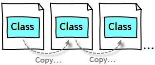
Instead of re-creating those classes again and again in different diagrams, Visual Paradigm allows you to “re-use” them. Through simple copy and paste (Ctrl-C and Ctrl-V), you can easily copy a shape from one diagram to another. Each shape is formally known as a “view”. So with this, you can create multiple views for a model element in representing different contexts. Changes made on a shape are all synchronized to other instances that appear in other diagrams without extra effort. This is great, but there is a drawback though.
Imagine you have two diagrams and they both contain the same class. In the first diagram the class is placed inside a package X, later on when you are working on the second diagram, you moved the class to a package Y. So now, the class is visually placed under two different packages in two diagrams, which package should the class belong to in model level?
To avoid confusion, Visual Paradigm adopts the concept of master view. A master view is simply the specific view of model element that decides the placement of that model element within a model hierarchy. It can be a shape on a diagram, or the representation in Model Explorer. When you create a model element the first time, either by drawing a shape or by creating a model element under Model Explorer, the created view will be treated as the master. Subsequent views are all known as auxiliary views. When you attempt to move a master view to another parent shape, you are updating the real model structure as well (as reflected in Model Explorer). However, when you move any auxiliary view to a different parent shape, there will be no change at all on the model structure.
The idea of master view provides a means to decide which model element (or root) should be selected as the parent of a model element. In this article, we will explore how to manually set a master view.
Setting/Changing a Master View
Before we go into the steps, let’s take a look at the sample project we use to demonstrate the function of setting a master view.
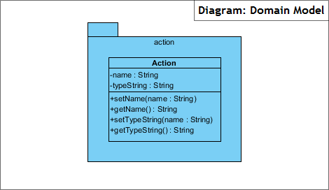
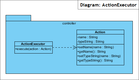
In this project, there are two class diagrams – Domain Model and Action Executor. The class Action exist in both diagrams. The view of Action in Domain Model is the master view, while the view in ActionExecutor is the auxiliary view.
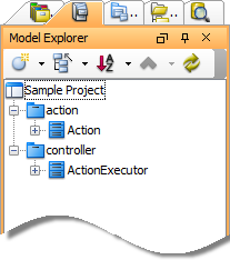
That’s why in model level, the Action class is placed inside the action package, following the master view in Domain Model diagram.
In this article, we will set the view of Action class in ActionExecutor diagram to be the master view. We expect that the Action class will be moved to the controller package automatically. Let’s start.
- Open the ActionExecutor diagram.
- Right click on the Action class and select Related Elements > Show Other Views… from the popup menu.
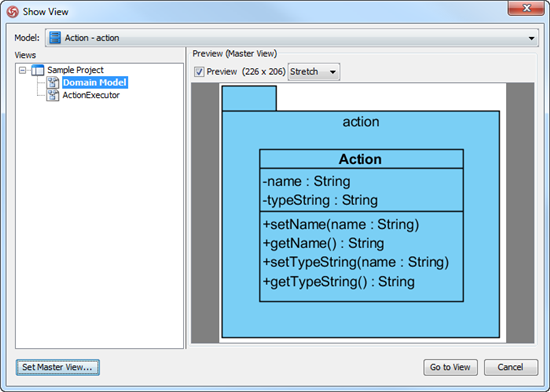
- This shows the Show View window. It lists out all the views of the Action class. Click Set Master View…at bottom left corner.
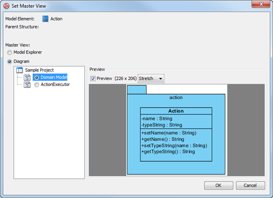
- This shows the Set Master View window. You can select on the left hand side the Model Explorer or a specific diagram to be the master view of selected element. To select Model Explorer means that the placement of model element will always follow the hierarchy as presented in Model Explorer. Any re-positioning made in views in any diagram will not affect the model hierarchy.
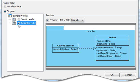
In this case, let’s select the view in ActionExecutor to be the master view.
- Click OK.
- Check the Model Explorer. You can see that the Action class is now placed under the controller package.
Related Articles
- Know-how – How to Show All Levels of Preview Shapes
- Know-how – What to do if you cannot resize shapes in your existing diagram
- Know-how – Showing and hiding resource icons




Is it possible to have two model elements (UML class or ER Entity) with a same name without them being connected as views?
For example: I have two ER diagrams, they both have an entity named “BusinessCase” but both diagrams show BusinessCase in different contexts. Visual Paradigm automatically identifies the other as the auxillary view and synchronizes it. While this is definitely useful, I want to show only certain columns in the first ER diagram and different columns in the second ER diagram (or properties/methods in two class diagrams) and keep the same name.
I mean – this is logically still the same entity having just one set of columns (eg. columns A, B, C, D, E, F), but I want to show different sets for different diagrams (eg. in first diagram only columns A, B, E, F and in second diagram only columns B, C, D). Is that possible?
You can create two model with same name in two model. Following is the steps
1. Go to Project Browser
2. Create two models (e.g. System Level, User Level”
3. Create ERD / Class diagram in each model
4. Than, you can create the same name class / entity.
* Please see the enclosed screenshot about how to create model
Hi Motig,
We have just read again your case and we think that to create two entities with same name is not an ideal solution because, in your case, the two entities are really the same. It’s just you want to show different columns in different situations.
The best solution is to hide the columns you don’t want. To do this, right click on your entity in ERD and select Presentation Options > Show Columns Mode > Customized… from the popup menu. Then, you can select the columns to show or hide.
Hope this helps!