How to Model Permissions on Use Case for Actors
In use case diagram, associations between actors and use cases are explicitly shown. We can see it clearly when an actor carries out a use case (or goal) from a line drawn between them. However, what if an actor does not carry out a use case but do refer to the output from it? How do we model that?
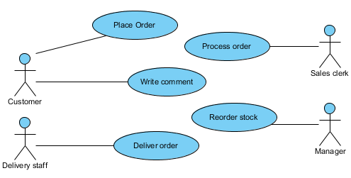
For example, the manager reorders stock but he/she may refer to orders placed by customers (while he/she does not actually carry out the order placing).
In this tutorial, we will show you one way to model relationships that are not so explicit. We will make use of chart diagram to create a matrix to store the permissions.
First, in a new chart diagram, we’ll create a new code type called Permission and 3 possible values under it – Read, Write and Execute. Then, we’ll create a matrix to list all combinations of actors and use cases (i.e. associations). In cells where appropriate, we use one of the 3 values to describe their associations. For example, if an actor actually carries out a use case, we give it the value, Execute. If an actor refers to output from a use case, we describe the relationship by the value, Read.
Note: The following example is shown using Visual Paradigm for UML (VP-UML) Professional edition.
Steps to Model Permissions
-
Define your own permissions code
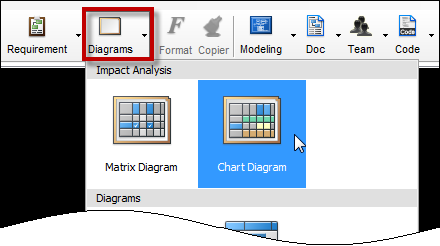
Go to the toolbar on the top. Click on Diagrams > Chart Diagram.
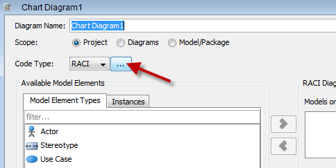
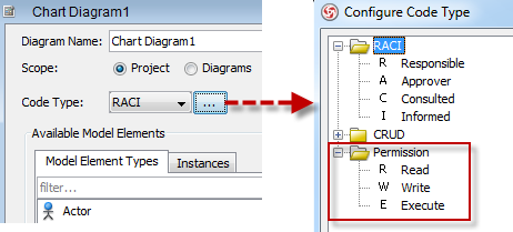
In the new chart diagram, locate the Code Type field and click the … button to the right.
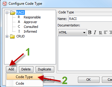
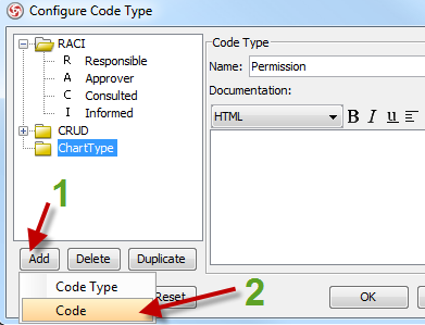
In the dialog box opened, (at the lower left corner) click Add and then select Code Type.
Enter Permission for code type.
Next, we’ll add 3 new codes under the Permission code type that we’ve just created.
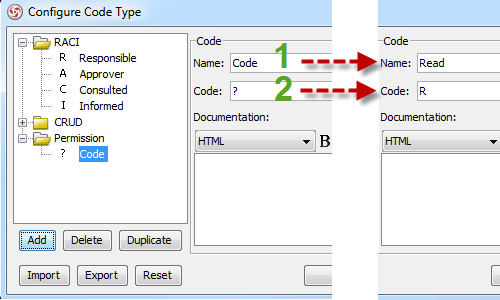
To add a new code, click Add and select Code.Enter Read for Name. Then enter R for Code.
To add the second new code, just click Add and select Code again.
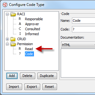
You’ll notice that the Read code we’ve just created shows up in the list and that to the right, it is ready for you to enter another new code.Repeat to enter the following 2 codes.
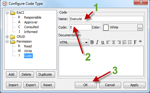
Name = Write; Code = W
Name = Execute; Code = E
After you enter the Execute code, click OK.Note: Clicking OK will close the dialog box above. But if you want to look at your new list of codes, you can always click the … button to open it again.
-
Set up a permissions matrix
In this section, we’ll set up a matrix to display all combinations of actors and use cases.
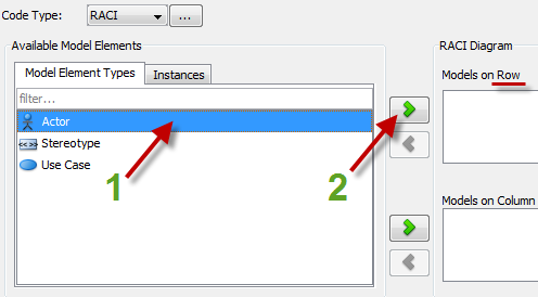
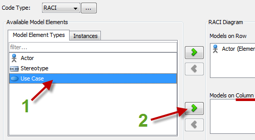
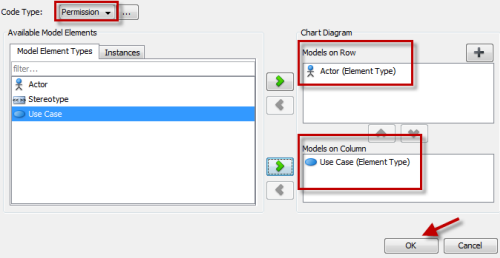
To specify the matrix row, select Actor and then click the top green right arrow.To specify the matrix column, select Use Case and then click the lower green right arrow.
Remember the Permission code type we added earlier? This is where we’ll put it into use.
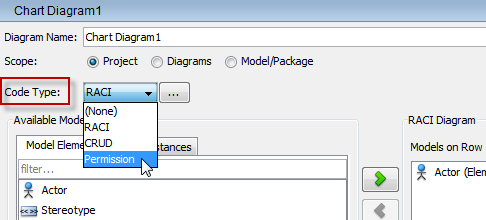
To specify possible values that can go into the individual cells of the matrix, go to the Code Type field.
Click the down arrow to the right and select Permission.Click OK.
-
Set permissions for individual actors on various use cases
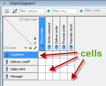
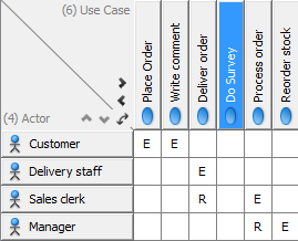
In the matrix opened, you’ll see the 4 actors in rows and the 5 use cases in columns. Each cell in the matrix represents a combination of an actor and a use case. In it, that’s where we are going to specify the corresponding permissions (Read, Write or Execute).
A lot of times, we’d probably begin with the first row and column. But here, we’ll look at another combination first, just so we can address the manager’s case which is mentioned in the beginning of this tutorial. Then we’ll look at the other cases.
To model that the manager is authorized to reorder stock
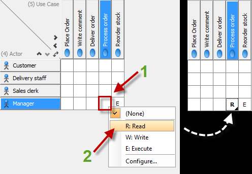
Right click on the cell that intersects Manager and Reorder stock. Select E: Execute from the list. E should appear in that cell.To model that the manager can have a look at sales orders
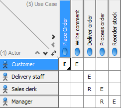
Right click on the cell that intersects Manager and Process order. Select R: Read from the list. R should appear in that cell.Repeat to set the remaining permissions as shown.
- Customers place orders (E) and write comments (E) for feedback.
- Delivery staff makes delivery (E) for items ordered.
- Sales clerks process orders (E) and sometimes refer to delivery orders for information (R).
So what happens to the matrix if I add a new use case afterwards?
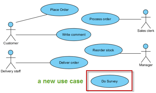
Let’s just say that we add a new use case called Do Survey to the use case diagram (after we’ve completed the matrix with the steps above).
If you return to the matrix, you’ll see that a new column called Do Survey has been inserted into the matrix to reflect the new addition to the diagram.
Related Links
- VP-UML Features – Use Case Diagram
- Watch this tutorial in YouTube
- How to import Microsoft Visio stencils
Related Articles
- How to List Out All Use Cases in the Current Project
- Customize the Order of Elements on Reports





Leave a Reply
Want to join the discussion?Feel free to contribute!