

Query Model Element’s Relationships using ETL Table
On-Demand Model ETL (Extract, Transform & Load) is a facility which allow user to query on their model elements (extract), manipulate them (transform) and further visualize them in diagram (load). The ETL table not just allow you to perform query on a single level of models, but also support nested levels such as the contained or connected elements. In this article we will show you how to configure the ETL table to perform query on 3 levels of model elements.
Here is the sample being used in this article. It consists of use cases, actors and requirements. We will perform the query by listing the actors which having Real Person stereotype, as well as its connected use case and also the requirement models which realizing that use case.
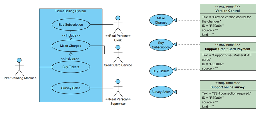
Example used in this article which having Actor associated with Use Case, and realized by SysML Requirements
To query on model element’s relationships:
- Select ETL Table element in diagram palette and drop it on any diagram.
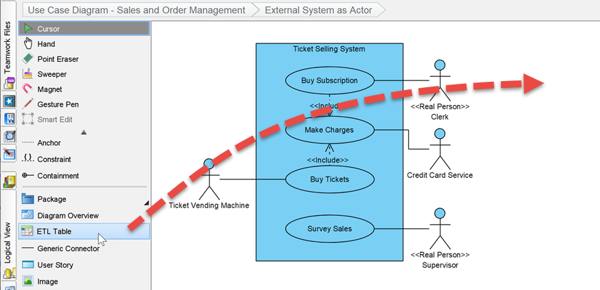
Create ETL Table in diagram
- Name the table if needed. When stop editing the name press Create Blank Table in Associate to Table dialog.
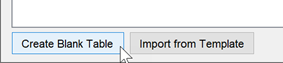
Create blank table
- A new application window will be pops out and showing the ETL Table editor.
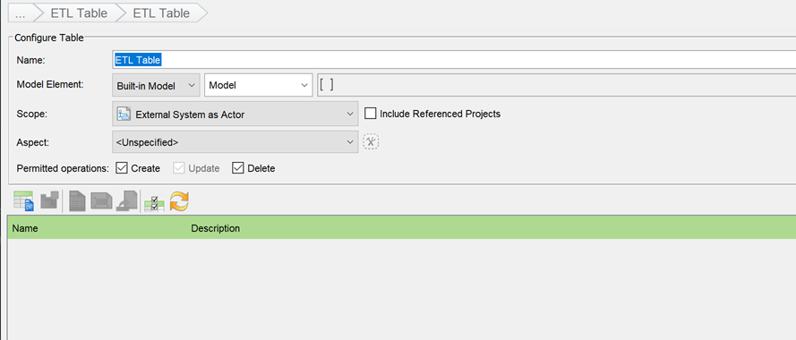
ETL Table editor
- Select Built-in Model in Model Element section, and choose the Actor model.
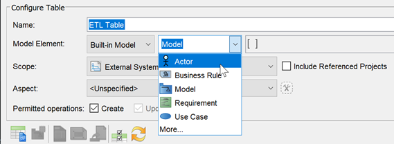
Select Actor as model type
- Press the [] button to bring up the conditions editor for defining filter criteria for the actors.
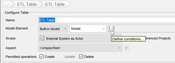
Define filter criteria
- In Conditions dialog select Stereotypes under Conditions column, then enter Real Person into the Value Press OK to close the dialog.
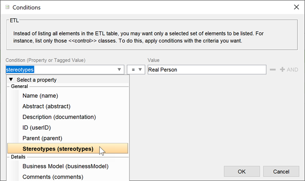
Filter by only search for actor with Real Person stereotype
- Now only the actors with Real Person stereotypes are being listed.
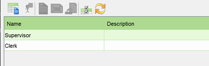
Only actors with Real Person stereotypes are now listed
- Press Configure Columns button to specify what being covered in the query.
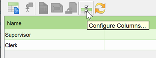
Configure Columns
- In the Configure Columns dialog we first remove the Actor’s Description from the table. Simply select Descriptions under Selected Column and press < button to remove it.
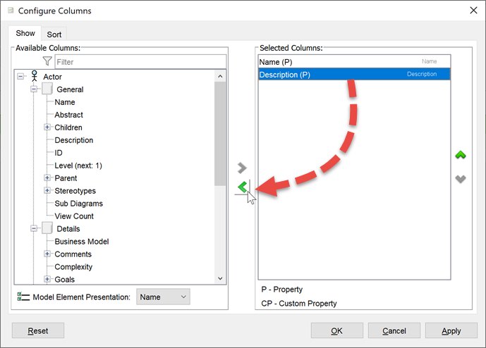
Remove actor’s description
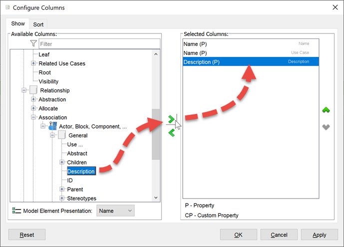
- Now we add the name if the use case to the table. In the Available Columns section, scroll down to locate Relationship > Association > Actor, Block, Component,… > General. After that select the Name property and press > button to add it to table.
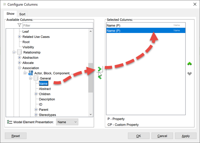
Add the name of associated use case to table
- Press the Configuration button next to the newly added column to change the column header to Use Case (to avoid confusion on duplicate column name in the table).
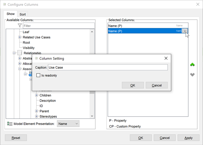
Rename column header to Use Case
- Repeat the steps 10 to add the Description property of the use case to the table.
Add use case description to table
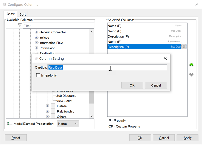
- Press Apply button then the name and description of the associated use case now listed in the table.
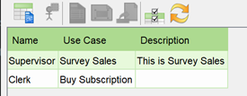
Table showing the user case associated with the actor
- Press the Configure Columns button again, this time adding the following properties:
Relationship > Association > Actor, Block, Component… > Relationship > Realization > GenericModel, Element > General > Name & Description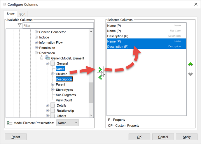
Add name & description of requirement which realizing the use case
- Change the name of the column header to Requirement and Req Desc. Press OK to close the Configure Column dialog.
Rename the column header for requirement name & description
- Now the requirement models realizing the use case are also being listed in the table.
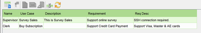
Requirements which realizing use case listed in table
- Switch back to original diagram the ETL Table will show as a legend of your diagram.
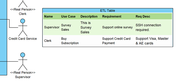
ETL table show as legend in diagram
Related Know-how |
Related Link |
Leave a Reply
Want to join the discussion?Feel free to contribute!