Reuse Constraint Parameters in SysML Parametric Diagram

The Parametric Diagram in SysML is a restricted form of the Internal Block Diagram. It shows the mathematical relationships between its modeled elements. Wish Parametric Diagram you can precisely define the details of a constraint in your system. The Parametric Diagram cannot live on its own, it must be relay on a SysML block, typically is a constraint block. In Visual Paradigm you won’t need to re-create the constraint parameters when you elaborate the constraint block with Parametric Diagram. In this article we will show you how you can reuse the constraint parameters when modeling in Parametric Diagram. Read more

How to override operations form superclass

Method overriding is a very common technique in object-oriented programming. It allows developer deliver specific implementation of a method in the subclass although it already defined by the superclass. When overriding a method the subclass replace the implementation in superclass by providing a method which exactly same as the one in superclass, i.e same name, parameter and also the return type. In Visual Paradigm you don’t need to redefine the operation in subclass to model the override. You can simply do it in one click inside the specification dialog. To override the operation: Read more

Why the relationships between entities not point to FK column?

tomcat-thumbEntity Relationship Diagram (ERD) is a tool for model the structure of a database. It mainly consists of the entity (database tables) as well as the relationships between them. Unlike the traditional UML diagrams, the relationship in ERD not just indicate the entitles are related to each other, it also specifies which column(s) between the source and target entities are linked, which also known as the primary key and foreign key relationship. People often want to have the relationships stick to its associated columns. But instead of manually adjust the connection point for the relationship connector, Visual Paradigm can automatically do it for you.

Read more

Switch from Classic Resource Centric Interface to Resource Catalog

tomcat-thumbThe Visual Paradigm Resource Centric interface is a handy feature for user to create diagrams without the need to memorize the syntax of the modeling language. It automatically filtered what you can do with the model element you working on in the diagram. In recent release Visual Paradigm enhanced the Resource Centric interface to become the Resource Catalog, which further boost the usability of the Resource Centric interface and make your diagraming task even easier. By default you will be switched to the Resource Catalog interface. But just in case you have missed the switch you can follow the details in this article to change the interface to Resource Catalog.

Read more

Model Entity with Custom Column Types

tomcat-thumbVisual Paradigm support wide range of databases for user to model the data structure of their systems. Once the data model is done you can generate persistent layer source code in Hibernate and use it as the out-of-the-box data access layer for building your database applications. All the data types which covered by Hibernate are directly supported by Visual Paradigm. But what if your model involved some domain specific data type which not covered by Hibernate? In this case you can make use of the User Type property to model it. To model with non-supported column types:


Read more

Specifying details for your association

Association is a very comment relationship between classifiers. The association is not a simple connector, it carry lots of information related to the relationships between classifiers. Those information may/may not presented on diagram, but they are vital to the definition of your models. In Visual Paradigm there are several ways to define the details for your association and in this article we will show you one by one. Read more

How to create different notations in a single diagram

Visual Paradigm supported modeling with various notations, including the Unified Modeling Language (UML), System Modeling Language (SysML), Business Process Modeling Notation (BPMN), Entity Relationship Diagram (ERD), Data Flow Diagram (DFD), Organization Chart, etc… When creating diagrams very often you may want to cross reference the notations from other diagram type, or even from other notation standards. In Visual Paradigm you can do it easily by customizing the diagram toolbar. In this article we will show you how it works. Read more

Show Details of Model Elements in Tabular Form

When the default attributes do not suffice to describe your model elements, you can add your own custom ones by using tagged values. These custom attributes can be added to model elements in various diagrams, such as an actor in use case diagram.

So if you are looking at model elements in a diagram, just how do you show their tagged values? This tutorial will show you how.

As an example, we will walk you through how to show tagged values associated with devices in an ArchiMate diagram.

Read more

Working with Master View

When your project is simple, you are able to express all of the design ideas with just a few diagrams. The diagrams are simple and self-explanatory. Each of them represents a distinct design idea and there is no overlapping between diagrams.

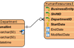
When you are dealing with a complex project, you may need to draw multiple diagrams to represent different contexts. You need to borrow shapes from a diagram to make them appear in other diagrams (i.e. contexts). In fact, this is extremely common when modeling with class diagram and business process diagram. Take UML class diagram as an example, there may be a domain diagram that presents all the entity classes and, another diagram that presents the associations and dependencies between a specific controller class and its related entity classes. So in this case, both diagrams contain the same set of entity classes.

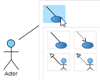
Instead of re-creating those classes again and again in different diagrams, Visual Paradigm allows you to “re-use” them. Through simple copy and paste (Ctrl-C and Ctrl-V), you can easily copy a shape from one diagram to another. Each shape is formally known as a “view”. So with this, you can create multiple views for a model element in representing different contexts. Changes made on a shape are all synchronized to other instances that appear in other diagrams without extra effort. This is great, but there is a drawback though.

Read more

How to Generate Unique ID for Model Elements

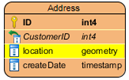
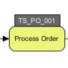
ID is a very useful property for a model elements. Having an unique ID for your model elements not just can ease the communication between your team but also help to structure your model in a more systematic way. Visual Paradigm can help you to generate unique ID for your model elements. Besides, you can apply customized patterns to the ID to accommodate your needs in different situations. In this article, we will show you how to configure the ID generator to generate customized ID for your model elements with Visual Paradigm. Read more